Home
Home
About Geosun
About Geosun
Products
Products
- Hardware
- Mobile LiDAR Scanning System
- gCollector Road Information Collection System
- gSpin POS System
- PPK Solution
Support
Support
News
News
Contact Us
Contact Us
Background
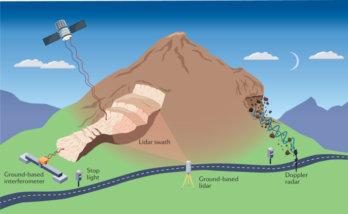
Landslides represent a serious geological hazard. The construction of many large-scale infrastructure projects, such as highways, railways, and reservoirs, involves excavation of mountainous terrain, which increases the risk of landslides. This necessitates the use of a cost-effective, easily deployable, and efficient monitoring method to monitor potential or active landslides, thereby avoiding unforeseen losses caused by large-scale landslides. GPS technology offers advantages such as all-weather operation, automation, flexible site selection, and simultaneous measurement of the three-dimensional position and velocity of points. Therefore, it provides an effective means of data acquisition for landslide monitoring.
GPS satellite positioning technology has significant characteristics and advantages compared to traditional surveying methods. It is not affected by weather conditions, does not require line of sight between points, and is capable of accurately positioning over long distances. Additionally, GPS enables real-time measurement, with good automation and integration capabilities, making it particularly suitable for dynamic and static safety monitoring and fulfilling complex measurement tasks required for large-scale construction projects. In recent years, GPS has been widely applied in deformation monitoring and precision engineering surveying fields due to its unique advantages.
Introduction
In the field, receivers or automated sensors send real-time monitoring data to the monitoring center. The monitoring center processes and stores the received data for different sensors and provides services externally. Clients connect to the server to request real-time and historical data for plotting and analysis.
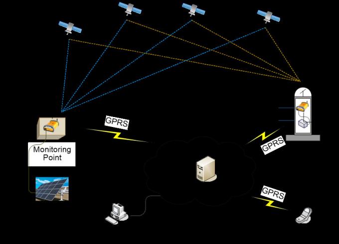
Geosun high-precision real-time deformation monitoring system consists of five subsystems: data acquisition subsystem, data transmission subsystem, data analysis and processing subsystem, display and warning subsystem, and real-time deformation monitoring management center. The real-time deformation monitoring management center serves as the data management center for the entire solution, while the data analysis and processing subsystem functions as the real-time GNSS data analysis and calculation center, which is also the core of the high-precision real-time deformation monitoring system.
Real-time Deformation Monitoring Management Center
It can effectively perform real-time monitoring of system operation. According to the actual project requirements, it can use databases such as Access, MS SQL Server, Oracle, etc., for data management and user management after calculation. It facilitates parameter settings, local/remote status browsing, local/remote data download, and data sharing. The data center is automatically backed up regularly to achieve 24-hour, 7-day-a-week, 365-day-a-year, round-the-clock unattended monitoring, ensuring that the system remains operational in the long term, meeting real-time monitoring requirements, and saving subsequent manpower resource costs.
Data Acquisition Subsystem
The data acquisition system consists of a reference station, monitoring stations, outdoor power supply, lightning protection system, and related equipment protection devices, forming a supporting system for guarantee. Key equipment utilizes self-developed high-precision real-time GNSS receivers, with hardware design suitable for long-term, continuous, stable, and precise monitoring requirements, ensuring real-time and accurate data collection. The high-precision real-time GNSS receivers designed for the high-precision large-scale facility deformation monitoring system, compatible with BeiDou and multi-mode GNSS, will achieve a precision of: Planar: ±(2.0mm+1x10⁻⁶D), Vertical: ±(4.0mm+1x10⁻⁶D).
Data Transmission Subsystem
The data transmission system can be built using transmission media such as RS232, dedicated wired/wireless ADSL Modem, optical fiber, wireless GPRS, wireless CDMA, UHF wireless radio, etc., making the system architecture flexible and versatile. The system not only supports on-site data download via drag and drop but also enables remote real-time data TCP/IP transmission and FTP file download. It can support data flow from over 100 observation points per monitoring area at maximum.
Data analysis and processing subsystem
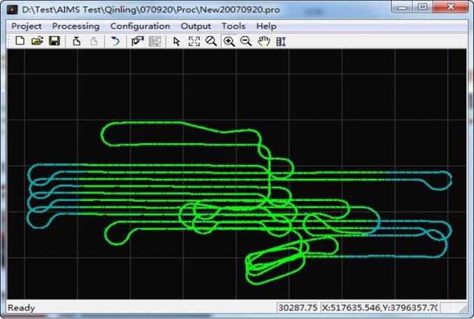
The data analysis and processing subsystem first converts and cleanses the GNSS raw data obtained from the collection devices through the data conversion function module, unifying them into the KRT format, an industry-standard calculation format. The standardized data undergo baseline calculation, least squares adjustment, coordinate transformation, output, and accuracy assessment by the calculation core module. The processed data is then delivered to the data analysis subsystem of the monitoring management center, where parameters such as accuracy and sensitivity analysis, baseline stability analysis, deformation time series, spectrum analysis, deformation visualization output, display, etc., are performed. To meet the needs of real-time monitoring systems, the data analysis module can perform continuous real-time data processing for long periods and provide data compression (4:1), storage, transfer, file management, printing of various reports, etc. Advanced Kalman filtering integrated with single-epoch integer algorithm is used for data calculation, making the data analysis and processing capability extremely powerful, with diverse analysis angles and rich means. It can calculate three-dimensional displacement components and deformation rates in all directions, easily achieving millimeter-level positioning accuracy, ensuring stable system operation and data reliability.
Display Warning Subsystem
The Geosun Space Monitoring and Early Warning System can display real-time operational status information of monitoring points on the terrain and landform images of various monitoring areas. It can automatically generate deformation time-history curves, deformation distribution maps, and multi-factor correlation graphs based on analysis and calculation results. It is capable of generating three-dimensional simulation graphics based on field topographic data, and producing contour maps and gradient chromatograms of deformation fields, as well as deformation field profiles. Additionally, it can perform preliminary analysis and data statistical evaluation of other monitoring data. It can determine risks based on preset warning threshold values, display real-time alerts in red on the screen, and issue alerts through alarm sounds, text messages, and other forms of multi-channel status information dissemination. In emergency situations, it can timely broadcast warning messages through multiple channels and forms (including operational technical personnel, unit leaders, information centers of higher-level management departments, etc.).
Hardware
The Geosun Space Monitoring and Early Warning System utilizes domestically developed GNSS receivers, the ROCK T100 or T200. Depending on the project requirements, users can flexibly choose between these models. The T100 is a single-frequency receiver, while the T200 is a dual-frequency receiver. Additionally, the system is equipped with GNSS antennas and adapters that are compatible with the receivers. Please refer to the diagram below for more details.
The Rock receiver T200
The main technical parameters of the Rock receiver T200
|
Project |
specification |
|
Tracking Channel |
72-channel GPS:L1 C/A code,L2C,L1/L2 GLONASS :L1 C/A code and P code, L2P code、L1/L2 Beidou-2: B1 C/A、B1/B2 |
|
Positioning Accuracy |
Static: Planar: ±(2.5mm+1×10⁻⁶D) Elevation: ±(5.0mm+1×10⁻⁶D) Dynamic: Supports Real-Time Kinematics (RTK)/Post-Processing Planar:±(10mm+1×10⁻⁶D) Elevation: ±(20mm+1×10⁻⁶D) Precision in conjunction with Stone RT system software Real-time static 3mm Daily Observational Accuracy 1mm |
|
Initialization |
Initialization Time: Less than 30 seconds Initialization Reliability: more than 99.9% Storage: 1GB Support MicroSD:2GB |
|
Data Logging |
Default Sampling Rate: 1Hz Highest Sampling Rate: 20Hz Storage Format: Raw Observation Format, RINEX Download Method: Network Download |
|
Communication |
RS232 RJ45 Differential Correction Message: CMR,CMR+,RTCM2.3,RTCM3.0,RTCM3.2 (compatible to Beidou) |
|
Power Supply |
7-18V, standard voltage 12V, power 4W |
|
Work Environment |
Work temperature: –40℃ ~ 65℃ Storage temperature: –45℃ ~ 85℃ |
|
Remote Access |
Web Page Access |
|
Physical Dimension |
length: 200mm;width: 142mm;height: 74mm;weight: 850g |
System Operating Interface
Automated monitoring solution
Inventory: Receiver, GNSS antenna, RF cable. Additionally required: Ethernet cable, PVC conduit (for protecting cables), weatherproof enclosure, router; for continuous power supply, UPS can be used.
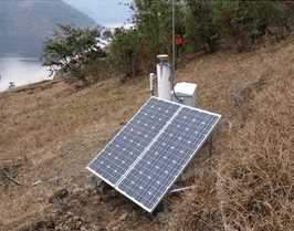
Power Supply: The power supply system mainly consists of solar panels, a power controller, and batteries. The power controller is a device specialized in controlling the solar panels/wind turbines, batteries, and supplying power to the receiver. Here, we'll explain using solar energy as an example. Solar panels generate electricity, which is then transmitted to the solar power controller. The solar power controller charges the batteries and supplies power to the receiver. During overcast conditions or at night, the solar power controller utilizes the battery power to supply the receiver. Alternatively, if wind energy is used for power, the solar panels can be replaced with wind turbines.
Protection: Generally, protection can be achieved by placing the batteries, solar power controller, and receiver inside a weatherproof enclosure. Additionally, installing a protective fence within a 2-meter radius around the observation pier can prevent damage from human or animal interference.
Lightning Protection: Lightning rods are installed at both the benchmark station and the 5 monitoring stations as preemptive measures against lightning strikes.
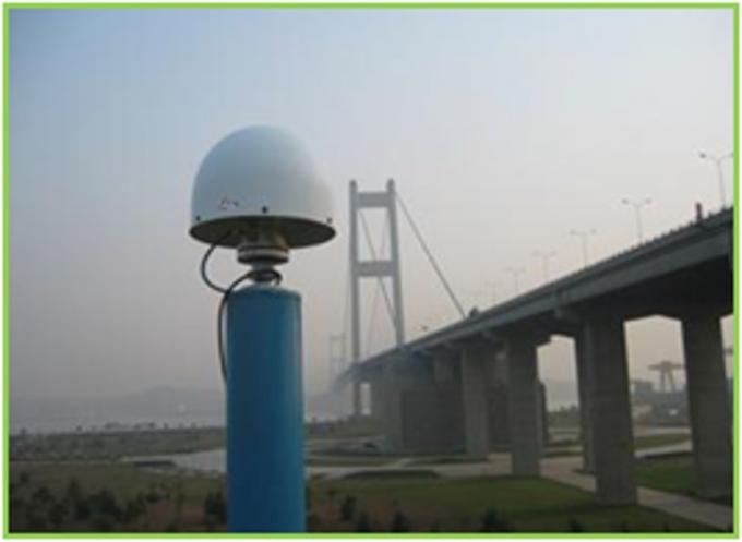
Antenna Mounting: In deformation monitoring, it's necessary to secure the GNSS antenna to the monitoring point. After establishing the deformation monitoring observation pier, a forced centering plate is installed, followed by concrete pouring. To avoid obstruction, the external antenna is typically positioned 1.5 meters or more above the ground level. Relevant documentation on setting up observation piers can be referenced for guidance.
Communication: The communication method depicted in the diagram combines wired and wireless bridge communication. Since the benchmark station provides the reference signal, it's crucial, so whenever possible, wired cable communication should be employed to ensure communication quality. For monitoring stations, a wireless bridge communication setup is preferred to avoid the difficulty and cost of laying cables. Simply connect the RJ-45 network interface of the receiver to the wireless bridge peripheral, and configure it for wired transmission in the receiver's web management interface.
Remote Monitoring Center: According to the design of the monitoring center, the system needs to transmit monitoring results remotely to the monitoring center located in Shanghai. Therefore, the Stone RT monitoring software is set up in the local server room as shown in the diagram below, and monitoring results are transmitted remotely to the remote monitoring center via the Internet.
Remote Landslide Monitoring System Structure
Implementation plan
Site Selection for Base Stations
When using Stone RT for deformation monitoring, attention should be paid to the selection of base station sites, following the principles below:
1. According to GB/T 18314 regulations, benchmark points should be buried for measurement outside the deformation influence range.
2. The site should have an open field of view near the station and be free from strong magnetic interference.
3. The site should have good transportation and communication conditions nearby, facilitating contact and data transmission.
4. The surface near the site should be covered with shallow vegetation to suppress multipath effects.
5. For locations where personnel are scarce or difficult to reach, avoid disturbances from idle bystanders.
6. Points should be established in stable and easily preservable locations.
7. Power supply should be reliable to ensure equipment operation.
Device configuration
Baseline Station Equipment Configuration Table
|
Project |
Model |
Specification |
|
|
Equipment |
GNSS receiver |
ROCK T200 |
Reference Station Professional GNSS Receiver |
|
GNSS Antenna |
AT504 |
Choke Ring GPS Antenna for Multipath Suppression |
|
|
UPS Power Supply |
|
2.2kV/24h, with control interface |
|
|
Baterry |
|
Sealed Maintenance-Free Valve-Regulated Lead-Acid Battery (12V-100Ah) |
|
|
Router |
|
Router with VPN Support, Built-in Firewall, Fixed Wide Area Network Interface, Optional Wide Area Interface WIC Card, and Fixed Local Area Network Interface: 10/100Base-T/TX |
|
|
Switch |
3Com3C6794 |
Switch Hub,8个10/100M interface |
|
|
Surge Protection Device |
HELITA pulsar18 |
Lightning Rod |
|
|
MCG SF80 |
Power Line Protector |
||
|
Auto STAC |
ST3000W Power Voltage Regulator |
||
Engineering installation
The tasks involved in the design and construction of each benchmark observation pier structure and civil engineering works include: preparing suitable materials, constructing foundations, building concrete observation piers, interfacing with GNSS antennas, and laying required cable conduits, among others. The construction and installation of benchmark station systems are carried out according to the table below, and the deliverables required for each process are also listed in the table.
|
Procedure |
Item |
Content |
Submit deliverables |
|
|
1 |
Selection point |
Site selection, environmental testing |
Summary Report on Benchmark Site Selection Techniques |
|
|
2 |
Benchmark station design |
Building, structure, installation, construction, etc. Overall design |
Report on Benchmark Station Architectural Design Overall Design Report for Reference Station |
|
|
3 |
Construction of civil engineering |
Construction work |
Construction of instrument piers, workshops |
Report on Civil Engineering Work for Reference Station |
|
Piping installation |
Laying of power, communication, and other pipelines |
|||
|
4 |
equipment installation |
Outdoor equipment installation |
GPS antenna, meteorological equipment, lightning protection system |
Design Report for Surge Protection Devices" "Installation Report for Surge Protection Devices" Installation Reports for Each Device |
|
Power supply system installation |
Surge protection devices, UPS power supply |
|||
|
Indoor equipment installation |
GPS receiver, communication equipment, host |
|||
|
5 |
Fine-tuning |
Unit Testing for Each Component |
Testing of Individual System Units |
Reference Station Testing Report Summary Report on the Construction of Reference Stations |
|
The overall testing of the reference station. |
The overall testing of the reference station. |
|||
Detailed construction details can be referred to GB/T 18314 'Specifications for Global Positioning System Surveys' for guidance on construction.
In addition, it is recommended to use wired communication for network communication at the base stations to ensure the real-time transmission of data and prevent delays in monitoring point data caused by delays in base station data. For engineering applications with less stringent real-time requirements, wireless GPRS network transmission can be used.
Site selection for monitoring points
Select based on on-site engineering requirements, while considering the site requirements for GNSS signal reception, which are generally similar to the principles of base station selection.
The installation of monitoring stations
According to the design scheme shown in the diagram, construct the monitoring point platform.

The typical installation structure

on-site installation

GNSS reference station

GNSS monitoring station
Central Data Center Construction
The overall requirements for central data center construction are as follows:
1. The construction of the data center must comply with the latest national standards, namely GB50174-93 'Code for Design of Electronic Computer Rooms'.
In terms of the decoration of the data center engineering, overall consideration should be given to factors such as waterproofing, moisture-proofing, lightning protection, dust prevention, anti-static measures, and electromagnetic shielding to ensure its safety. Regarding the selection and use of decoration materials, national standards and specifications should be followed.
2. The overall design of the data center should be scientific, with reasonable distribution, simple processes, and convenient operation and management. It should comprehensively consider advancedness, safety, and economy.
In terms of internal construction of the data center, various aspects need to be considered, including the composition of control systems, network conditions, cable routing, and fire safety. Main components include the data center's air conditioning and ventilation system, power distribution system, emergency UPS power supply system, and monitoring system. Additionally, there are safety considerations for grounding systems, lightning protection systems, and fire suppression systems. The layout of power, network, and server connections should be scientifically planned to eliminate potential safety hazards.
3. The expenses for the data center should be strictly controlled within the budget range, ensuring practicality in all aspects while also achieving economic efficiency and savings.


